
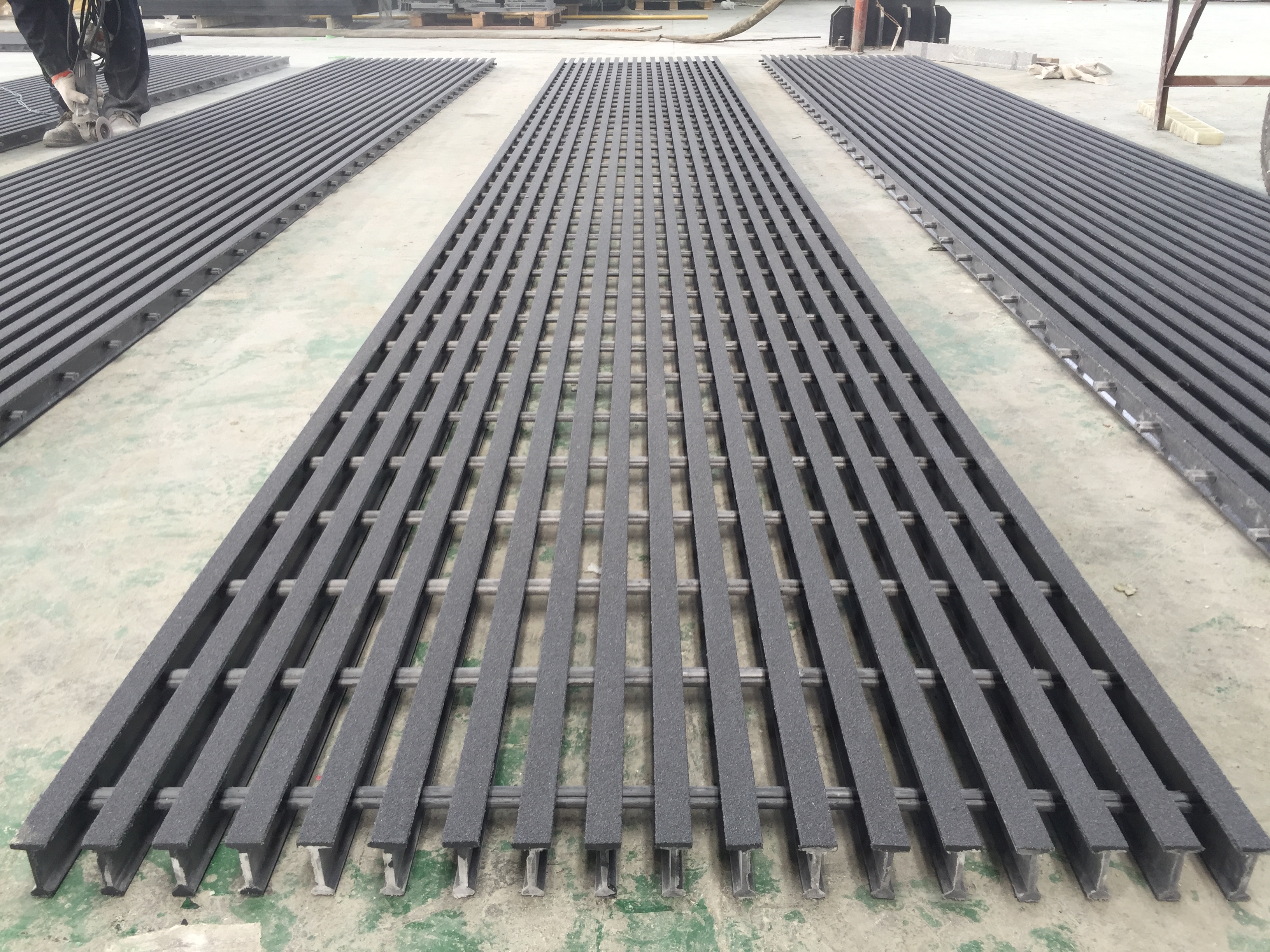
MACHS supplied workshop photograph of pultruded grating. Representative family photograph; geometry and report applicability require separate verification.
FRP grating selection starts with the installation, not a thickness alone. A useful technical enquiry defines where the panel is supported, how the load is applied and which acceptance criteria the project requires. This guide helps you prepare those inputs before asking whether a particular configuration is suitable.
The examples use the recorded I6015 configuration and T5020 configuration. They do not provide an allowable-load rating or approve either model for an installation.
1. Draw the supports and the panel outline
Provide a plan showing supporting members, panel boundaries, bearing direction, openings and fixing positions. For pultruded grating, the direction of the bearing bars matters: rotating a panel changes the relationship between the bars and the supports.
Distinguish the following dimensions rather than using “span” for all of them:
Swipe the table sideways to read every column.
| Input | What the purchaser should identify |
|---|---|
| Clear span | The unsupported distance between the relevant support faces |
| Support centres | The spacing between support centre lines, identified separately from clear span |
| Bearing contact | The support width and the actual contact arrangement |
| Panel and cut-outs | Finished outline, openings, edge conditions and any additional supports |
| Orientation | Bearing-bar direction relative to the proposed supporting members |
A cut-out, an unsupported edge or an assumed support that is absent from the final installation changes the question being evaluated. Show these conditions on the drawing before requesting a load assessment.
2. Describe the load case without mixing units
Give the load value, unit, location and contact area. A uniformly distributed load and a concentrated load are different inputs; a wheel or equipment foot should not be described only as a load per square metre.
- For distributed loading, identify the loaded area and the project load requirement.
- For a concentrated load, identify the magnitude, position and contact dimensions.
- For equipment or moving loads, provide the relevant operating information and the project’s required treatment of those loads.
- State the deflection criterion and who is responsible for approving it.
Do not turn a maximum, ultimate or failure load into a working load by renaming it. Ask which design basis, support conditions and acceptance criteria apply to the proposed supply. This guide does not supply an assumed safety factor or a universal deflection limit.
3. Match the actual section and material
The MACHS catalogue records an I-6015 reference with 38 mm depth. The linked 2014 report separately describes an isophthalic polyester I6015 specimen of 38 mm thickness. These two records answer different questions: catalogue geometry helps identify a section, while a report describes its tested specimen and method.
T5020 is associated with an approximately 50 mm-thick specimen in its linked 2026 report. Neither the 38 mm nor the 50 mm description establishes the allowable span for your load case. Review the bar section, spacing, resin, surface, fabrication and support conditions together.
4. Check what the technical document actually tests
The linked I6015 sample report is report 101490735SAT-001A, issued on 15 January 2014 under ASTM E84-13a. The linked T5020 sample report is report 260811011SHF-002, issued on 26 August 2026 under ASTM E84-26a.
Both concern surface-burning characteristics. Neither document should be used as a structural working-load table. A matching model name or nominal thickness does not establish that the current ordered resin, surface or fabrication matches a tested sample.
Use the technical-resource centre to check the recorded document identities, scope and release status. Read the complete original rather than relying on a cropped result or a certificate logo.
5. Resolve drawing and version gaps before release
The current I6015 record includes three candidate drawings carrying the same printed A0 revision but showing different panel or cut-part geometries. A0 alone does not identify an approved replacement sequence or establish a connection to the test specimen.
The T5020 record also retains a historical manual-versus-report depth discrepancy and catalogue mass differences. Those differences should be resolved against a controlled drawing and the proposed supply, rather than silently normalised in a quotation.
Ask for the applicable drawing number and revision, material and surface definition, fabrication details and the supporting load evidence for your stated conditions. Identify who accepts any remaining open items.
An I6015 enquiry example without an invented capacity
For an access-walkway enquiry, mark the I6015 bearing direction on your support plan. Enter the actual clear span, load case, contact area and deflection requirement. State full-panel or finished-cut-part quantities, and identify the required resin, surface and documents.
If a load or acceptance criterion is undecided, mark it for review. The useful output is a clearly defined technical question, not an unsupported statement that 38 mm depth is sufficient.
Prepare the next decision
Return to I6015 parameters and technical documents or T5020 parameters and technical documents. For commercial scope, use the quotation-comparison guide.
The enquiry brief below carries the selected configuration into the form. Attach your actual support drawing and mark unresolved conditions; no project-specific allowable load has been released in this article.
Related buyer FAQ · Review application conditions · More buying questions
Review evidence · Discuss your requirement
Frequently asked questions
Is panel depth enough to determine an allowable span?
No. The bearing-bar construction and direction, support contact, clear span, load type, contact area and acceptance criterion must be considered together. Send the actual support plan for review.
Can the linked ASTM E84 reports supply missing load data?
No. They describe surface-burning tests of identified specimens, not structural working-load tables. Request evidence for the actual support and loading conditions.
What should be done when a drawing or load condition remains open?
Identify the drawing number and revision and mark the unresolved input. The enquiry checklist allows a technical review request without inventing a capacity or acceptance limit.
Related technical resources
Related products
I6015 pultruded gratingI6015 pultruded FRP grating for walkways and equipment access. Compare the recorded geometry and sample-report scope, then send your span, load conditions and cut sizes for quotation review.T5020 pultruded gratingT5020 pultruded FRP grating for walkway and platform selection. Check the catalogue geometry and separate report scope, then send your support layout, cut sizes and required surface for review.Your enquiry brief
Selected model(s): carry the chosen configuration; identify any requested alternative separately.
Application and service environment:
Drawing number, revision, units and approval status:
Panel sizes, quantities, cut-outs and bearing-bar direction:
Supports, bearing contact and clear span:
Load type, magnitude, units, position and contact area:
Deflection / acceptance criterion and approving party:
Resin, surface, fixings and required technical evidence:
Unconfirmed inputs and requested review:
Destination and required date:
Ready to discuss this requirement?
Carry this checklist into the enquiry form, fill in what you know and mark unresolved items for review.
Use this brief in your enquiry